
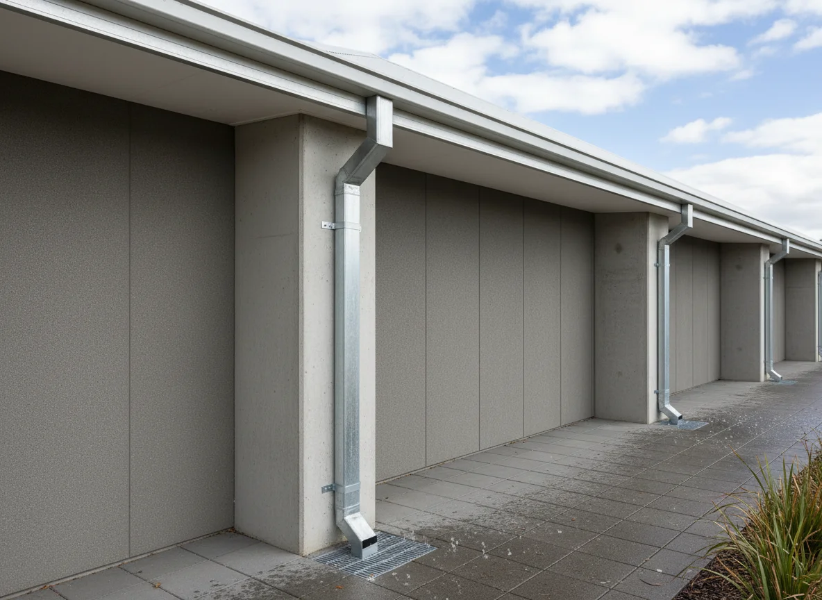
Begin at the gutter outlet. That is where the downpipe route becomes a physical sequence rather than a note that says supply pipework. From the outlet, the run may drop straight for a while, step around an eaves line, pass a fascia or cladding projection, return to a wall face and finish at a nominated lower connection. Each change along that route needs to be visible before a rectangular section or offset is ordered.
A clear specification follows the water path without pretending to design the drainage system. It names the upstream component, records the movement of the pipe, separates straight sections from offsets and keeps material, finish and visible faces beside the relevant item tags. If the route cannot be followed from top to bottom, the request is not ready for fabrication or supply.
The sketch should therefore read like a descent. First comes the outlet. Then comes the upper drop. Then the change of plane. Then the lower drop and connection. That order makes the measurement conversation easier because the supplier is not being asked to assemble a route from scattered length notes.
Outlet First: Name the Starting Component
The starting point may be an eaves gutter outlet, box-gutter sump, rainhead, nozzle or custom connecting piece. Name it. A rectangular downpipe order should not begin with a length if the upstream connection is unknown. The outlet tells the reader where the pipe begins and which face of the building the route serves.
The first view should show the outlet relationship and the direction of drop. A front elevation can identify the building face. A small side view can show whether the pipe sits proud of the wall, below an eaves line or close to cladding. If the pipe changes direction immediately below the outlet, show that movement before listing quantities.
For product context, Wesroof’s steel roofing and building materials page includes stormwater components such as large downpipe sections, sumps and connecting pieces, alongside sheets, tophats, battens, purlins and patio components. Use the order notes to identify which stormwater component family the request belongs to.
Track the First Drop before the Offset
Once the outlet is named, follow the first vertical drop. Mark the upper section before jumping to the offset. This matters because a step around a fascia or projection is only understandable when the straight portion above it is clear.
Use already-approved outlet positions and keep the route clear on the drawing. Do not ask the supplier to size or relocate the drainage system.
A useful first-drop note can state the tag, elevation location, upstream outlet and direction of fall. If there are several pipes on the job, repeat the tag on the schedule and the drawing. A pipe called DP1 on the elevation should not become a nameless rectangle in the quantity list.
Keep the Label at the Connection
Where the outlet is beside another roof-edge component, keep the label close to the connection. A sump, rainhead or gutter outlet may control the first piece in the route, but it should not be confused with the pipe section below. That distinction helps the drawing stay component-based rather than turning into a single stormwater sketch.
Measure the Change of Plane
An offset downpipe exists because the route cannot stay perfectly plumb. Wesroof keeps that route with the fabrication enquiry. It may need to move from the gutter line to a wall, step around fascia, clear cladding depth or align with a lower connection. The offset is the change of plane, so the drawing should show the direction of the move before it shows the final count of pieces.
Use plain directional language. Aluminium pressings may sit in the same pack when the project names that material. Does the pipe move back to the wall, out from the wall, left, right or around a projection? A side elevation often explains forward and backward movement better than a front view. A small plan view can remove doubt where the offset moves sideways.
Avoid relying on the phrase standard offset unless the project team and supplier already share a fixed meaning for that item. Stainless steel pressings may sit beside a named stainless run. One building may need a small step at the eaves. Another may need a more deliberate route around a cladding plane. The drawing should turn that route into visible geometry rather than asking the workshop to infer it from a photograph.
For each offset, show where the straight section stops, where the angled or formed section begins and where the lower drop resumes. Metal cladding can sit beside a related wall face. If the offset relates to a rainhead, sump or custom connector, keep that relationship beside the component tag.
Describe the Offset by Movement
It also helps to describe the offset by movement rather than by appearance. Light fabrication may apply if several prepared parts become one supplied item. A note such as step back to wall or clear fascia line is more useful than a bare adjective. The movement note can sit beside the section view while the schedule carries the item name, quantity, material and finish.
Turn the Path into Named Pieces
After the outlet, first drop and offset are mapped, convert the route into named pieces. A simple top-to-bottom sequence might read as outlet connector, upper drop, offset set, main drop, intermediate join and lower shoe or connection if that part is specified. The exact names can follow the project’s schedule, but the order should preserve the same sequence as the drawing.
Custom folded work needs measured information rather than a loose email note. Wesroof’s custom metal flashings and construction pressings page states that bespoke flashings, gutters, downpipes and specialised trims are manufactured from site-specific measurements and architectural drawings. For a downpipe route, those measurements should sit with the named pieces they control.
If accessories are being supplied by another party, do not include them in the shop item count. The FAQ covers how we take an enquiry and what we do not install. Show enough context for the pipe pieces to make sense, but keep the supply list honest. A bracket decision, wall penetration or installed support may belong elsewhere even when it affects how the pipe is drawn.
Name Each Piece in Sequence
This naming sequence reduces later confusion. A formed rectangular pipe, an offset set, a sump and a matching flashing can sit close together on the same elevation, but each has a different job. The schedule should not mix those jobs into one broad stormwater line.
Keep Finish Notes Beside the Visible Faces
Material and finish are not afterthoughts for rectangular pipework. Name them from the project documents.
For a supply request, the practical action is to state the nominated material, finish and visible face for each tagged pipe section or offset. Do not let the word steel stand by itself if the project specification calls for a particular coating, colour or prefinished face.
A rectangular section may have a front face, side faces and a wall face. If a prefinished material is nominated, say which face matters in the finished elevation. Where several downpipes serve different elevations, keep the colour and finish notes with the relevant tags rather than in one general paragraph at the end of the schedule.
Late Boundary: Supply Information, Not Drainage Design
The boundary belongs here, after the route has been mapped. A supply drawing can show the outlet relationship, pipe path, offset geometry, material, finish, visible faces and quantities. It should not ask the supplier to calculate catchment, size the drainage system, approve overflow strategy, inspect site conditions, certify compliance or decide whether the installed arrangement is suitable.
The handover point comes after the downpipe route, offsets, connection faces and quantities have been confirmed. About Us covers the fabrication and supply scope. Fabrication and materials supply can then follow the specified information, while design decisions stay with the responsible project team.
This late boundary is useful because it does not interrupt the measurement sequence. First the reader traces the outlet, drop, offset and lower connection. Then the article draws the line between what can be supplied and what must already be resolved.
Hand Over the Downpipe Route
Before requesting pricing, read the drawing from the top connection to the lower end without skipping a turn. If the path disappears behind fascia, cladding or a projection, add a side or plan view. If the material or visible face is unclear, add a note. If the outlet position or downpipe count is not approved, pause the supply request until the project documents settle it.
A handover set can be compact: marked elevation, small offset view, component schedule, material and finish note, quantity list and current revision. Keep photos as supporting context, not the main instruction. A photograph can show the building face, but it rarely replaces the route, tags and measurements needed for a formed component.
When those files are ready, Contact us to check the current rectangular-section and offset scope. Bring the route from gutter outlet to lower connection.

Leave A Comment