
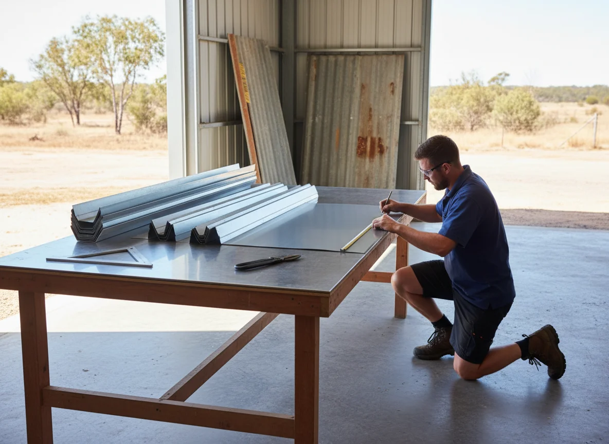
A corrugated-junction sketch often reaches the folding bench with one useful idea and several missing views. The roof line is marked, a flashing shape is suggested and a length may be noted, but the workshop still has to ask how the folds relate to the sheet profile. Before fabrication, the drawing needs to let someone follow the part section by section without guessing the roof.
Think of the sketch as a route around a shaped surface. One face sits over or beside corrugations, another face turns away, a colour side may be exposed, and a related trim may be handed to the opposite end of the roof. If those relationships are visible on the page, a corrugated roof flashing request becomes a measured supply conversation rather than a loose description of metal to bend.
The useful question at this early stage is not whether the sketch looks complete at arm’s length. It is whether each section gives the folding bench enough context to keep shape, orientation and finish together. A brief mark-up that shows the sheet face, the first turn and the exposed side can be more valuable than a polished plan that never explains how the metal meets the corrugations.
Bench Sketch: Identify the Roof Junction
The first check is the junction name. Is the item for a ridge, barge, apron, valley, wall line, penetration, change in pitch or a custom trim that belongs to a larger roof package? The label matters because it tells the reader why the fold exists. A valley piece, an apron and a capping may all be folded steel, but they do not solve the same meeting of surfaces.
Once the junction is named, mark the roof plane that gives the part its context. A plan view can show location, but a small section usually explains the metal. The section should show the sheet profile, the fold direction, the face that remains visible and any adjoining material that affects the way the shape is read. Where the drawing shows only a finished strip, the fabricator may see a neat shape without seeing the roof condition behind it.
For bespoke folded items, Wesroof’s custom metal flashings and construction pressings service is the relevant product reference. That page supports custom flashings, gutters, downpipes and specialised trims made from site-specific measurements and architectural drawings. It does not remove the need for the drawing owner to define the junction and the required form.
Section One: Profile Direction and Sheet Face
Corrugated and ribbed sheets create direction. A flashing may run along the pans, cross the profile or sit around a local interruption. Manufacturer guidance separates longitudinal and transverse flashings because a fold that runs with the sheet is not read in the same way as a fold that crosses crests and pans.
The drawing should therefore answer three profile questions. Which way do the corrugations run? Which edge of the flashing faces upslope or downslope? Which face will be visible after fitting? These questions are small, but they prevent a plan view from being mistaken for a complete instruction.
If a flashing crosses the profile, the section should make the crossing obvious. Aluminium pressings or stainless steel pressings may sit in the same pack when the project names those materials. Metal cladding can sit beside the flashing when a wall face is in the drawing. Light fabrication may apply if several prepared parts become one supplied item. If it runs with the profile, the note should say so rather than leave the workshop to infer the direction. If the same job needs left-hand and right-hand pieces, show the mirrored condition or state it plainly. A single sketch of one hand can be misleading when the opposite side is needed.
Length Versus Developed Width
This is also the place to separate overall length from girth or developed width. Stainless steel pressings may sit in the same pack when the project names that material. A length note says how far the item runs. A girth or developed-width note describes the material path around the bends. Keeping those ideas apart makes the shape easier to check.
Where the drawing has both plan and section views, compare them before adding a revision note. Metal cladding can sit beside the flashing when a wall face is in the drawing. The plan may show the item in the right location while the section quietly reverses the fall or visible face. That kind of mismatch is not a fabrication detail to be solved later. It is a drawing-readiness issue that should be corrected before the file leaves the project team.
Section Two: Fold Path, Hands and Colour Side
After the profile direction is clear, read around the fold path. Light fabrication may apply if several prepared parts become one supplied item. Start at a nominated edge and follow each face in order. Mark inside and outside angles where the drawing could be read two ways. Show returns, hems, downturns or upturns as part of that path, not as afterthoughts floating beside the sketch.
The drawing should be fully dimensioned, with relevant angles marked. If the flashing is prefinished, the colour side should be marked, especially when that face turns around a corrugation or sits beside cladding.
A practical section-by-section check can be simple. Wesroof keeps that check with the fabrication enquiry.
Fold Path Checklist
- start point and first face
- fold direction for each turn
- visible face or colour side
- left-hand, right-hand or paired item
- piece tag used on the drawing and the quantity list
- matching items that share the same profile direction
These notes do not decide the roof design. The FAQ covers how we take an enquiry and what we do not install. They make the nominated pressing readable. If one item depends on another, such as a capping beside an apron or a trim beside a penetration sleeve, give each one a tag so a later check does not merge them into one generic flashing.
Section Three: Material Note and Compatibility Flags
Roof flashing materials should not be inferred from the nearest roof sheet or from the word steel by itself. About Us covers the fabrication and supply scope. The drawing should state the nominated material and finish, then point to the project documents if compatibility or coating decisions have already been made by the responsible party.
The drawing should name the material and finish so the folded piece is not inferred from the nearest roof sheet. That is a supply note, not a universal roof detail.
Wesroof’s steel-roofing source gives the related product context for sheets, tophats, battens, stormwater components, purlins and patio components. For wider material coordination, the steel roofing and building materials page is the internal reference to keep with a roofing package. If the drawing includes roof flashing materials beside sheets or stormwater items, list the flashing separately so its material and finish are not buried inside a general roof order.
When the material decision is unresolved, mark it as information required before fabrication. Do not let the fabricator select a material by implication. The safe instruction is the specified material, finish and colour side, not a guess about suitability.
Drawing Audit before the Wesroof Boundary
Read the Drawing in Fold Order
A useful audit reads the drawing in the same order the metal will be understood. First identify the junction. Then confirm the profile direction. Next follow the fold path. After that, check handed pieces, exposed faces, material notes, quantity and revision. If the drawing changes view between plan, elevation and section, make sure the same tags appear in each place.
This audit can be marked directly on the drawing. Circle the start edge, tick each fold that has a direction, underline the material note and check that the visible face is still visible after the part is mirrored or paired. If one piece is repeated in several lengths, keep the shared profile information once and the length or quantity differences beside each tag. That keeps the drawing concise without forcing the fabricator to infer which note applies to which item.
The audit should also remove general commentary that does not help fabrication. Site access notes, installation descriptions and compliance conclusions can distract from the shape if they are not already approved project instructions. Keep approved reference numbers where they help identify the detail, but do not ask the supplier to resolve roof pitch, drainage capacity, waterproofing strategy or regulatory acceptability from a sketch.
Only after that audit does the supply boundary need to be stated. At the fabrication stage, the shop can work from the checked drawing and confirmed material notes rather than reconstructing the junction from an abbreviated description. The request should cover fabrication and supply of nominated metal parts, while design, approval, certification, inspection and site fitting remain outside the supply brief.
That compact boundary protects the drawing. It keeps the workshop focused on the formed component and keeps unresolved project decisions with the people responsible for them.
Hand Over the Files without Turning the Detail into Design
The final handover should feel like a clean drawing set, not a long correction email. Put the section, plan or elevation views together. Keep the item tags consistent. Attach the quantity list, material and finish notes, colour-side instruction, handed-piece note and current revision. If the same roof package also includes sheets, gutters or trims, separate those items so each component can be reviewed on its own path.
Before sending, ask one narrow question: can the nominated shape be followed from one edge to the other without solving the roof? If the answer is no, add the missing view or note before requesting pricing. If the issue is design suitability, send it back to the project team rather than hiding it in a fabrication request.
When the drawing is ready, Contact us to send the marked files. Bring the sketch, sections, material nomination, finish notes and quantities.

Leave A Comment